Create a Use-case Diagram for the System Described Here Scribd
Remember effective use cases must have understandable actors and goals. Notation of System Boundary Subject is a rectangle with Systems name on top of the rectangle.

Design Document For Library Management System Management Computer Science Library
Use cases are a set of actions services and functions that the system needs to perform.

. The two main components of a use case diagram are use cases and actors. Click Software from the Template Category and then double click Jacobson Use Case icon to start a new page. Use Case Relationships Associations.
Actor in a use case diagram is any entity that performs a role in one given system. Its drawn as an oval and named with the function. Where use cases are used to represent the set of activities services that the system needs to perform and actors are the entity that works under.
A user placing an order with a sales company might follow these steps. Identify the Actors Customer is the only person in involved in our system. Use case is a special flow of events through the system.
A use case must help the actor to perform a task that has some identifiable value. The primary use case consists of a standard flow of events in the system that describes a standard system behavior. Identify the actors and add them to the workspace outside the system boundary.
Browse catalog and select items. Then translate Use Case sequence into Diagram. It details a set of actions between actors and the data consumed and produced if any.
Then translate Use Case sequence into Diagram. This simply means that the actors communicate with the systems use case. A use-case diagram may contain all or some of the use cases of a system.
A user placing an order with a sales company might follow these steps. A UML use case diagram is the primary form of systemsoftware requirements for a new software program underdeveloped. UML use case diagram is one of the types of UML diagram which is used to represent the dynamic diagram by mapping the structure of the systems using actors and use cases.
This diagram represents inheritance among use cases. It means that some of the variables functions are something else is inherited from parent to child. Describe the functionality and users actors of the system.
Receive conformation number from salesperson. You can start drawing the use case diagram with Createlys use case diagram tool which comes with a simple drag and drop interface and intelligent use case diagram shapes that make drawing easier. Listed below are some important components of Use Case diagrams.
Use Case Diagrams A use case diagram describe an interaction between a user and a system. A UML use case diagram is the way to model system requirements for a new software system being developed. UML is the modeling toolkit that you can use to build your diagrams.
Built-in Use Case Symbols Start a New Use Case Diagram Drawing Page 1. A use case represents a distinct functionality of a. Instead they show the planned or actual flow of processes that can be expected when using the program or software.
Identify the first event triggering event 6. Begin with a Use Case. Begin with a Use Case.
The primary use case represents the normal expected and successful completion of the use case. Indicate the communication between an actor and a use case. Once you have identified your actors and their goals you have now created your initial list of high level use cases.
Start Edraw on the File menu point to New. These are dynamic diagrams. Object Oriented Design and Analysis Introduction Use-cases are descriptions of the functionality of a system from a user perspective.
Actors things outside the system use cases system boundaries identifying what the system should do interactions or relationships between actors and use cases in the system. It describes different actions that a system performs in collaboration to achieve something with one or more users of the system. Since we are making an automation tool.
A use case diagram displays the relationship among actors and use cases. Identify the Actors role of users of the system. The use case diagram is a special case within this group since it depicts what behavior is expected from a system or software program in a specific use case.
Use case diagrams are responsible for visualizing the external things that interact with the part of the system. Inheritance in use case diagram. This could be a person organization or an external system and usually drawn like skeleton shown below.
Browse catalog and select items. A use case represents a function or an action within the system. Show the relationships between the actors that use the system the use cases functionality they use.
Use case diagrams model the functionality of a system using actors and use cases. An actor is a user playing a role with respect to the system. A Use Case model can be developed by following the steps below.
Identify the next event and the objects involved 8. Use cases specify the expected behavior what and not the exact method of making it happen how. On the left a library for Jacobson Use Case Diagram is open.
Stick figures represent actors in the process and the actors participation in the system is modeled with a line between the actor and use case. Receive conformation number from salesperson. Depict the behaviour of the system as it appears to an outside user.
Start by drawing the system boundary and giving a name to the system. A use case is an artifact used in system analysis to identify define and organize system requirements. So what is a use case diagram.
Use cases once specified can be denoted both textual and visual representation ie. How to Draw a Use Case Diagram. They show the.
All the commonly used symbols are included. Use case diagrams referred as a Behavior model or diagram. Use cases are represented with a labeled oval shape.
Draw dotted lines down indicating lifelines 5. Authentication is the parent use case and authentication by finger authentication by info are child use cases. In this context a system is something being developed or operated such as a web site.
It is also referred to as scenario or functionality. Following are the common notations used in a use case diagram. Draw a horizontal arrow from the object that sends a message to the object that receives it 7.
Use Case Key Concepts Cont A measurable value. To depict the system boundary draw a box around the use case itself. Identify the features Look for the actions that our.
An actor is represents a user or another system that will interact with the system you are modeling. Identify what are the users required the system to be performed to achieve these goals. A use case is an external.
When diagramming a use case start by asking the users to list everything the system should do for them. A use case diagram is a dynamic or behavior diagram in UML. Use cases are used to represent high-level functionalities and how the user will handle the system.
It simply describes and displays the relation or interaction between the users or customers and providers of application service or the system. A key concept of. This can be done using.
8 Constructing Use Case Diagram for our Case Study Step 1. Here the term system is something being developed or operated. For each category of users identify all roles played by the users relevant to the system.
Developing Use Case Diagrams. Examples of systems are ERP systems POS systems etc. In comparison to other behavioral diagrams in UML the use case diagram is.
A use-case diagram can contain. UML Use Case Diagram.
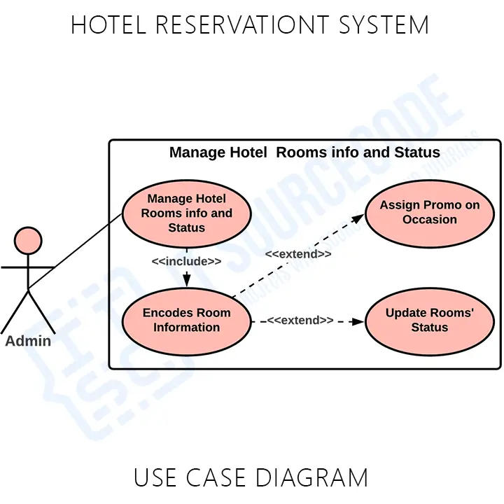
Hotel Reservation System Use Case Diagram Itsourcecode Com 2021
Pmo Pmis Ucd Use Case Diagram
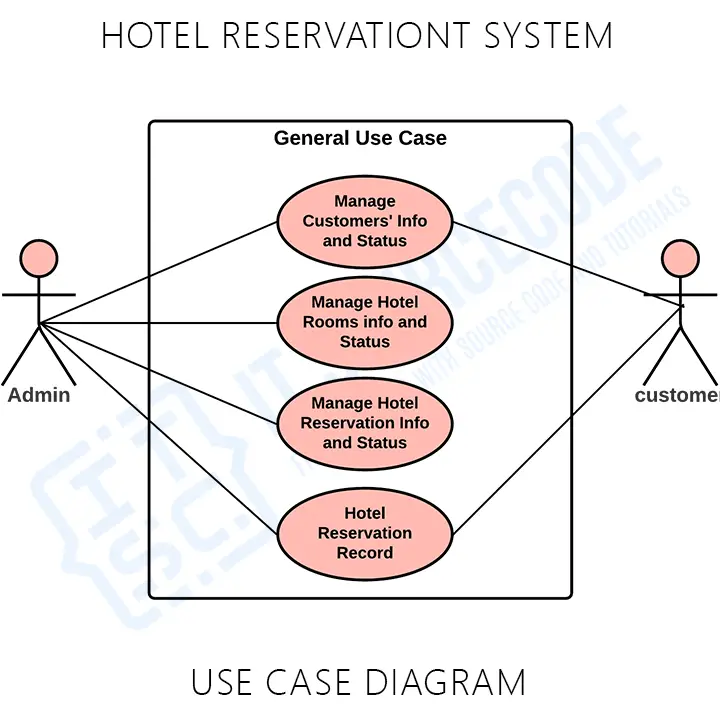
Hotel Reservation System Use Case Diagram Itsourcecode Com 2021
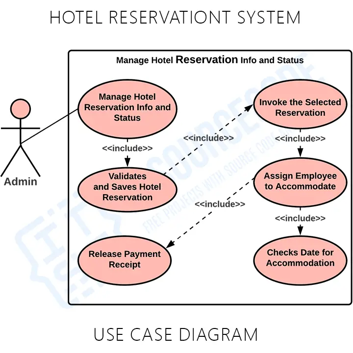
Hotel Reservation System Use Case Diagram Itsourcecode Com 2021
Comments
Post a Comment